Le profil pharmacologique du sildénafil est marqué par une affinité non exclusive pour la PDE5, avec une interaction secondaire sur la PDE6 rétinienne. Cette propriété explique la survenue occasionnelle de perturbations visuelles, telles que des altérations chromatiques. Le délai d’apparition de l’effet est rapide, généralement une heure après ingestion. Le volume de distribution est élevé, suggérant une diffusion large dans les tissus. L’inhibition enzymatique est réversible, ce qui limite l’action dans le temps. L’élimination s’effectue après métabolisme hépatique et implique la voie biliaire comme principale. Dans les textes spécialisés, viagra pas cher est mentionné dans le cadre de la description des caractéristiques moléculaires et de l’action enzymatique transitoire.
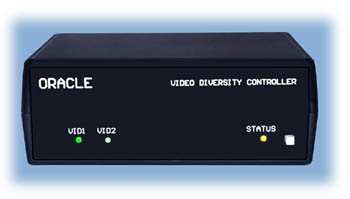
Oracle diversity controller
VIDEO DIVERSITY CONTROLLER
The Oracle video diversity controller is usedto bridge two wireless video receiverstogether. Dual receivers can be used to helpreduce RF multi-path problems, as well asallow for other signal improving techniques. FEATURE SUMMARY
Universal wireless video receiver compatibility (NTSC or PAL).
Two channel audio support (stereo audio or voice/data).
Very high bandwidth. No A/V signal degradation.
No special installation requirements (uses standard RCA connectors).
Operates on 6VDC to 14VDC (90mA typical). WHAT IS IT? Oracle is an intelligent video switch with two A/V (audio/video) inputs that are merged into a single output. In a typical installation, it constantly monitors the video signals from two user supplied wireless video receivers. Whenever Oracle determines that the currently chosen A/V source has corrupted video, it automatically switches over to the other A/V source (if it is error free). The switching is very fast, which helps maintain A/V quality.
Oracle can be used to create a spatial diversity antenna system. This configuration involves
placing the antennas (from two receivers) at slightly different locations. As little as a few inchesapart is enough to offer some signal improvement. Spatial diversity is used to reducemultipathing interference, which is a common nuisance with RF wireless video systems.
It is also possible to install vastly different antennas on the two video receivers to enhance theoverall antenna performance. For example, you can combine a moderate gain patch antennaand a high gain directional Yagi for automatic switching from short to long range. Maybe youwant to extend the beamwidth of your antenna system? If so, then use two similarreceivers/antennas to nearly double the beam width. Or, perhaps pair up a 900Mhz and2400Mhz video system for the ultimate in frequency diversity and redundancy.
The antenna strategy you choose will depend on your operating environment and applicationrequirements. Although Oracle cannot eliminate all video problems, using it with a carefullychosen receiver/antenna setup will certainly help minimize reception issues.
ORACLE V1.4 2007-2008 DIGITAL PRODUCTS COMPANY
INSTALLATION Connecting Oracle to your wireless video receiver is a simple matter of plugging in the RCA cables (not included) to the unit’s rear panel. Below is a photo of the A/V connectors: A/V INPUTS
Connect this to the main/right audio output of A/V receiver #1.
Optional, connect this to the left audio output of A/V receiver #1.
Connect this to the main/right audio output of A/V receiver #2.
Optional, connect this to the left audio output of A/V receiver #2. VIDEO-1 :
Connect this to the composite video output of A/V receiver #1. VIDEO-2 :
Connect this to the composite video output of A/V receiver #2. A/V OUTPUTS VIDEO-A :
Connect this composite video output to the A/V monitor or recorder. VIDEO-B :
Spare video output (fully buffered) for additional monitoring equipment. AUDIO-R :
Connect this main/right audio output to the A/V monitor or recorder. AUDIO-L :
Connect this left audio channel output to the A/V monitor or recorder. POWER INPUT
The power input is a 2.1mm X 5.5mm DC Power Jack. The center pin is positive
r and the connector body is negative s. The applied voltage may range from6VDC to 14VDC (8-cell AA NiMH or 12V Gel-cell is typical). Note: A universal DC power cord is included. The white striped wire lead is the positive conductor.
ORACLE V1.4 2007-2008 DIGITAL PRODUCTS COMPANY
FRONT PANEL LED IDENTIFICATION Three LED’s and a pushbutton switch are located at the front. They are as follows:
Video-1 A/V input is the displayed source. Flashes if video is disconnected.
Video-2 A/V input is the displayed source. Flashes if video is disconnected.
Normally on, Blinks during low battery alert. FRONT PANEL PUSH SWITCH The front panel push switch is used to control several features: MANUAL VIDEO SWITCHING During normal operation, the video source can be manually switched by briefly pressing the pushbutton switch. A quick tap (less than ½ second) of the pushbutton switch is required. The automatic video switching is disabled for five seconds to allow temporary viewing of a noisy video source. After the short delay, normal video switching will be restored.
The safety timeout can be disabled by pressing the pushbutton switch for more thanthree seconds. A confirmation beep will be heard and the yellow Status LED will slowlyblink as a warning that the automatic switching is turned off. The manual switching modewill not revert back to normal operation until the pushbutton switch is pressed for twoseconds again (or DC power is removed). This feature is a toggle operation and can beused whenever you want to disable or enable the automatic video switching. LOW VOLTAGE ALERT A periodic beep warning will be heard if the low voltage alert has been enabled and the battery voltage is too low. The STATUS LED will also blink at a fast rate. To temporarily silence the alert, press the pushbutton switch for more than one second. The alert cancellation will be in effect until the battery voltage is returned to a higher allowed level. SYSTEM CONFIGURATION PROGRAMMING Oracle must be configured for your particular application. Please see the next section for system programming instructions.
ORACLE V1.4 2007-2008 DIGITAL PRODUCTS COMPANY
SYSTEM PROGRAMMING INSTRUCTIONS Oracle can be easily configured to your requirements. The system programming feature allows you to set the following parameters:
Low Battery Alert Voltage (6.0V - 13.9V).
Programming Oracle involves pressing the front pushbutton switch while observing the LEDindicators. The green VID1 LED’s blink pattern indicates the programming step. There are sixsteps, so there are six unique LED patterns that will be seen by the time programming iscomplete. The programmed settings are stored and are not lost when power is removed.
At each step you will respond by pressing the push switch. The number of presses will programthe feature. For example, during the “Video Type” programming step, pressing the switch twotimes will select the PAL video mode. Once you are done with the step, wait three seconds forthe yellow STATUS LED to wink once and it will move to the next step. If desired, programmingcan be exited by removing power after the yellow STATUS LED winks, which will leave theremaining values unchanged.
If a pushbutton response is not entered within seven seconds, Oracle’s green VID2 LED willreport the existing stored setting by blinking out its code. The setting will not change and youwill move to the next step. Note: If your entry is illegal, all three LED’s will rapidly flash forseveral seconds as a warning. You will then be allowed to try again.
The LED patterns are arranged as simple patterns of short and long blinks. The following table
outlines the blink codes ( = short blink, ,, = long blink). DESCRIPTION
Switching Sensitivity, 1=LOWEST, 5=HIGHEST
Video Level Balance Adjustment, 1=ON / 2=SKIP
ORACLE V1.4 2007-2008 DIGITAL PRODUCTS COMPANY
START OF PROGRAMMING
Programming begins by holding down the pushbutton switch while you apply power. Continue to press the switch until the yellow STATUS LED is on. The audio buzzer willalso begin to sound off. When you are ready start programming, release the switch. Nowthe fun begins!
This entry is used to set the video mode of your two wireless video receivers. Forexample, press once for NTSC video.
Step 2: Switching Alert Chirp
This entry is used to control the audio alert that is heard whenever the videosources are automatically switched. For example, press twice to disable the chirpnoise.
Step 3: Low Battery Alert Beep
This entry is used to control the low battery alarm beep. For example, press onceto enable the voltage alarm beep.
Step 4: ,, Low Battery Voltage (N)
Range: 6 to 13 VDC (in 1 volt increments).
This entry configures the low voltage alarm threshold. To set the alarm to 6.5V, press sixtimes. Note: the following step will be used to enter the remaining 0.5V value.
Step 5: ,, Low Battery Voltage (.n)
Range: 0 to 0.9 VDC (in 0.1 volt increments).
This entry is a companion to Step-4 and is used to enter the one-tenth volt value. For example, if the desired threshold is 6.5V, press six times at Step-4 and fivetimes at this step. To enter a “.0" value (i.e., 6.0), do not enter any key presses(wait a few seconds for the step to end).
ORACLE V1.4 2007-2008 DIGITAL PRODUCTS COMPANY
Step 6: ,, Switching Sensitivity
Range: 1=Very Low, 2=Low, 3=Normal, 4=High, 5=Very High.
The video switching criteria can be altered to suit your preference. When set toLOW, the video will switch less often (more video noise is tolerated). When set toHIGH, the video will switch more often (less video noise is tolerated). For mostusers the NORMAL setting is best.
Step 7: ,, ,, Video Balance Adjustment
The Video Balance Adjustment step is used to ensure that the wireless receivers’ videolevels are closely matched for best image quality. This adjustment should be madewhenever new A/V sources are installed. The balance feature requires that the brightestA/V source is connected to the VID2 input. Note: The balance adjustment is found on the bottom of the unit. A small screwdriver is required to adjust it.
During the balance adjustment mode, the green VID1 and VID2 LED’s will rapidly toggleback and forth. At the same time, the two video inputs will also toggle; what you will seeis the video from the two receivers in a ping-pong fashion. The goal is to adjust theirbrightness so that the two video sources look the same (or nearly so).
While watching the video image, carefully adjust the balance trimmer found near theVideo Out jack (see photo on the right). The best adjustment is found when the displayedvideo image has the least amount of perceived brightness “flicker.” When theadjustment is complete, press the pushbutton switch for at least two seconds to exit.
If the balance trimmer does not provide sufficient range, then it will be necessary toswitch the A/V-1 and A/V-2 input cable positions. This will ensure that the A/V source,with the highest brightness, is installed on the VID2 input. This is needed to allow properoperation of the balancing feature. Don’t forget to switch the audio inputs to match therelocated video cables. Note: If the battery voltage is too low the Video Balance feature will be disabled. Pleasecheck for a low battery alert if you are unable to enable this feature.
ORACLE V1.4 2007-2008 DIGITAL PRODUCTS COMPANY
DIGITAL PRODUCTS COMPANY 90 Day Limited Warranty
COVERAGE:This product is warranted to be free from defects in parts and workmanship for a period of 90 days. Digital Products Company (DPC) will repair orreplace (at its option) the product and any of its parts which fail to conform to this warranty. The warranty period begins on the date the productwas first purchased. This warranty is in lieu of all other expressed warranties. DPC does not assume or authorize any party to assume for it anyother obligation or liability. THIS WARRANTY GIVES YOU SPECIFIC LEGAL RIGHTS. YOU MAY HAVE OTHER RIGHTS, WHICH VARY FROM STATE TO STATE.
MODIFICATIONS:Any modifications or repair by anyone other than Digital Products Company (DPC) or its authorized agents will void this warranty.
NOT COVERED IN THE WARRANTY (EXCLUSIONS):1. Malfunctions due to improper installations, non-authorized repairs, tampering, misuse, dropping impact or modification. 2. Possible incompatibility with other A/V equipment. 3. Damage due to acts of God, lightning or accident. 4. Incidental or consequential damages, including damages from delay or loss of use, or equipment damage to other customer owned
5. Any product whose serial number has been altered, defaced or removed. 6. Batteries, cords, wall mounted transformers, cosmetic parts or routine maintenance. 7. Adjustment of customer-operated controls and features as explained in the instruction guide.
WHEN SERVICE IS NEEDED DURING THE WARRANTY PERIOD:1. Contact DPC using the “contact us” link instructions found at www.dpcav.com. Please provide the model name, serial number, purchase date,
and specific details to the problem. If DPC determines that service is required, they will issue a Return Authorization (RA) number and they willrequest that you return the unit.
2. Pack the unit in its original packing materials (or suitable equivalent) with all accessories. Place this in a larger shipping carton and include
sufficient filler to protect the unit from shipping damage. DPC is not responsible for shipping damage due to poorly packaged units.
3. Write the RA number on the outside of the shipping carton. Include inside the carton a note describing the problem, your name and STREET
ADDRESS, the RA number, and a photocopy of the sales receipt.
4. Ship the instrument prepaid and insured to Digital Products Company, 134 Windstar Circle, Folsom, CA 95630 USA. Your unit will be returned
to you using DPC’s preferred shipping method. Deliveries of warranty repairs outside the USA are at the customer’s expense.
WHEN SERVICE IS NEEDED AFTER THE WARRANTY PERIOD:1. Try to resolve the problem by contacting DPC’s technical support department. Please provide the model name, serial number, and a description
of the problem. You must provide your fax number or e-mail address if you are outside the USA.
2. If the technical support agent determines the problem requires service then DPC will issue an RA number and provide payment and return
Digital Products Company, or their distributors, have no control over the installation and use of theirproducts. As such, no liability may be assumed, nor will any liability be accepted, for any damagesresulting from the use of this product. Under no circumstances will the buyer be entitled toconsequential or incidental damages. Use at your own risk. By act of installing it, the buyer accepts allresulting liability. DIGITAL PRODUCTS COMPANY
ORACLE V1.4 2007-2008 DIGITAL PRODUCTS COMPANY
FREQUENTLY ASKED QUESTIONS Q: Can I power Oracle from the same 12V battery that operates my two video receivers? A: Yes you can. As a bonus, Oracle’s low battery alarm will tell you when the battery needs attention. Q: To reduce polarization reception problems, I would like to combine a vertical polarized antenna with one that is horizontally polarized. Will this help my 2.4Ghz “mobile” application? A: Perhaps, but it is not the ideal solution. To help minimize polarization dropouts, a better method would be to use circularly polarized patch antennas on your receivers. Then space these apart for spatial diversity. Q: I have a wireless public address system that I would like to improve with a diversity antenna setup. Can I use two audio receivers (no video) with Oracle? A: No. Oracle needs the video signals to perform the intelligent A/V switching. Q: I noticed that the audio level changes after the A/V sources have switched. Why is that? A: Although Oracle has a video balance adjustment, it does not have one for unmatched audio levels. If the problem is excessive, try inserting a series resistor on the audio signal of the loudest source. The exact resistor value will require experimentation (start with 1K ohms and go from there). Q: There are two video outputs but only one set of audio outputs. How do I install a second audio output? A: The audio output is specially buffered and can drive two audio inputs. All that is needed is an RCA “Y” cable, which is available from electronic suppliers. Q: Sometimes I still see bad video from my wireless receivers. I thought Oracle prevented such problems? A: Oracle determines which video source is error free and then switches to it. However, if both sources are corrupt, then the video will be poor until at least one source has good video. Q: Can I use the system with HDTV signals? A: No. Only composite NTSC/RS-170 and PAL/CCIR signals are supported. Q: Although the video will look fine, occasionally my receiver’s audio will have static noise in it or will fade away. It is definitely RF signal related. Why does it occur? A: That is a common behavior on some video receivers due to the way the audio sub-carrier is processed. Because Oracle only analyzes the video signal, it cannot correct bad audio.
ORACLE V1.4 2007-2008 DIGITAL PRODUCTS COMPANY
Q: Can I use Oracle to mix a 900Mhz video receiver with a 2.4Ghz video receiver? A: Yes. Some folks claim that this is the ultimate in diversity methods. Keep in mind that your video camera will probably need to be “buffered” with a video amplifier when it is connected to the input of the two RF transmitters. Q: I am not able to reliably toggle the video sources when I use the manual switching mode. When I press the pushbutton switch it does not seem to work. What is wrong? A: To toggle the video sources you must briefly tap the pushbutton switch. Do not press and hold it. This is because longer button presses are reserved for the low battery alarm silencing feature.
ORACLE V1.4 2007-2008 DIGITAL PRODUCTS COMPANY
ORACLE PROGRAMMING SUMMARY
Switching Alert ChirpRange: 1= On, 2= Off
Range: 6 to 13 VDC (in 1 volt increments)
Range: 0 to 0.9 VDC (in 0.1 volt increments)
Range: 1=Very Low, 2=Low, 3=Normal, 4=High, 5=Very High
DIGITAL PRODUCTS COMPANY
CALENDARIO DELLE GARE VALEVOLI PER I RANKING GIOVANILI 2014 Agg al 18 dicembre 2013 Gara Giovanile Circuito invernale Liguria Garlenda FEBBRAIO Trofeo Giovanile Memorial Pietro Manca Gara Giovanile Circuito invernale Liguria Gara Giovanile Circuito invernale Liguria Castellaro Gara Giovanile Circuito invernale Liguria Castellaro Race to Sutri Under 16 - 1ª tapp
FAQs on Alcohol Abuse and Alcoholism The National Institute on Alcohol Abuse and Alcoholism (NIAAA) routinely receives a variety of questions about alcohol. We would like to share the following frequently asked questions and their answers. It is important to understand that these answers are not meant to provide specific medical advice, but to provide information to better understand the he

 VIDEO DIVERSITY CONTROLLER
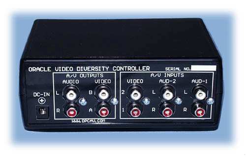 INSTALLATION
 FRONT PANEL LED IDENTIFICATION
 DIGITAL PRODUCTS COMPANY
 ORACLE PROGRAMMING SUMMARY