Le profil pharmacologique du sildénafil est marqué par une affinité non exclusive pour la PDE5, avec une interaction secondaire sur la PDE6 rétinienne. Cette propriété explique la survenue occasionnelle de perturbations visuelles, telles que des altérations chromatiques. Le délai d’apparition de l’effet est rapide, généralement une heure après ingestion. Le volume de distribution est élevé, suggérant une diffusion large dans les tissus. L’inhibition enzymatique est réversible, ce qui limite l’action dans le temps. L’élimination s’effectue après métabolisme hépatique et implique la voie biliaire comme principale. Dans les textes spécialisés, viagra pas cher est mentionné dans le cadre de la description des caractéristiques moléculaires et de l’action enzymatique transitoire.
February 2005 Manual No. 84-317-1 Rev. 2 2004, 2005 Fluke Corporation, All rights reserved. Printed in U.S.A. All product names are trademarks of their respective companies
Section 2: Operation. 2-1
Procedures for Using Models 34-317 and 34-317-7000 . 2-1
Introduction Section 1 Introduction 1.1 Introduction
These phantoms provide an effective means of monitoring the calibration of an ultrasound system. They contain precision-spaced groups of nylon monofilament targets, embedded in a medium that exhibits ultrasound responses similar to those encountered in human liver imaging. They have the same attenuation, scattering characteristics and propagation velocity as liver parenchyma. Also included are several sizes of simulated cysts, an encased cyst-like object, and solid tumor-like objects. The transducer rides along a flexible, smooth exterior surface that simulates human skin texture.
Ultrasound systems can be checked easily for linearity, axial and lateral resolution, ring-down, sensitivity, depth-marker accuracy and registration. Multipurpose Tissue-Cyst Phantoms provide a consistent medium that gives repeatable quantitative responses not otherwise obtainable with human subjects.
1.2 Description
The phantoms have a series of monofilament nylon targets, 0.240 mm (0.01 inch) D. Two sets of targets form resolution group patterns (A, Figure 1-1). The first is 3 cm from one side of the phantom, 18 cm from the other side. The second group is 13.5 cm from the first side, 7.5 cm from the other. Thus, resolution measurements can be made at any of four depths.
See Figure 1 for the Locations of the Following Internal Targets.
A. The resolution groups (A, Figure 1-1) have targets with center-to-center spacings of 5 mm, 4 mm, 3
mm, 2 mm and 1 mm for axial resolution tests. Each group has a second row of targets, nearly at right angles, to give simultaneous transverse resolution information. Spacings are 3 mm, 5 mm, 10 mm, and 15 mm. The axial rows are 10° from perfectly parallel and perpendicular to the phantom's outside surfaces to decrease acoustic shadowing of some of the monofilament targets by others. The distances from the phantom's surfaces are close to the focal zone distances of typical short, medium and long-focus transducers.
B. When scanned from the top, eight rods (B, Figure 1-1) are spaced at increasing distances within
the filling medium, starting at a distance 1 mm from the edge and increasing by 1 mm for each succeeding rod. This group is used for the rapid measurement of the transducer dead-zone or "ring-down" distance.
C. One group of parallel rods, 1 cm apart in a vertical plane, (C, Figure 1-1) is scanned from the top for
depth calibration, measurement of gain as a function of depth, and measurement of vertical linearity. This group also gives an indication of the acoustic beam shape with depth since the line target is generally displayed as a horizontal smear.
D. One group of horizontal parallel rods, 2 cm apart, is used for horizontal calibration and linearity
In the B-mode, both the vertical and horizontal grids should be imaged from all three scanning surfaces to measure the registration and linearity of the scanner and display.
Nuclear Associates 84-317 & 84-317-7000 Operators Manual
E. A diagonal row of four (Lo-S) simulated cysts (E, Figure 1-1) has cylinders of gel similar to the
background filling material of the phantom. The "cysts" (4, 6, 8 and 12 mm D.) have no scattering centers (hence "Low-scatter" or "Lo-S") and are "transparent' to the ultrasound beam.
F. Another row of four cysts (F, Figure 1-1), parallel to the first and of the same size, is filled with gel
having more scattering centers than the background material. It is labeled "Hi-S" (high scatter) and simulates solid lesions similar to tumors.
G. Six more "Lo-S" cysts are in two columns in the low right corner (G, Figure 1-1). Each column
contains a 2 mm, 4 mm and 6 mm cyst. One column is at 2.2 cm and the other at 4.4 cm from the side-scanning surface. These are used with short-focal-Iength transducers and scanners designed for close viewing.
H. One cyst-like object (Bounded Lo-S) (H, Figure 1-1) is encased in a highly reflecting plastic skin. It
represents normally fluid-filled organs such as the larger blood vessels.
The filling medium is a hydrogel containing a scattering agent that, at 72°F, simulates human liver parenchyma with respect to attenuation, scattering and propagation velocity over the range of frequencies used in ultrasonic scanning. Sealed into a sturdy plastic case, it requires little or no care. The scanning surfaces are made of soft plastic film that simulates skin.
Introduction
DO NOT USE EXCESSIVE PRESSURE WHEN SCANNING. The plastic case withstands normal handling and washing with water and soap. Store the phantom at room temperature only. For transporting the phantom or storing it at temperatures outside the 32° to 150°F range, we recommend the optional Insulated Carrying/Storage Case 89-317. Nuclear Associates 84-317 & 84-317-7000 Operators Manual Operation Section 2 Operation 2.1 Functions
The standard echo display level is an arbitrarily chosen pulse height on the oscilloscope display. It is for reference only, but should be the same for subsequent tests and should be recorded. For example, a 4 cm pulse height on an 8 cm high display might be used.
2) B-Mode and M-Mode Including Gray Scale Displays
The standard echo display level is an intensity level equivalent to an arbitrary number of gray levels above the zero display level. The level should be consistent and recorded. For example, a 3 dB level above the display zero or threshold might be used, but in any case the system should be well below the saturation level. Any scanning motion should be specified, e.g., sector scan with an effective linear speed of n cm/sec or an M-mode time sweep of n cm/sec.
Low gain settings can be used to image targets with minimum scattering. Higher gain settings will increase scattering effects and allow system performance evaluation at "clinical" settings.
Two targets are said to be resolved if the amplitude between the two echoes decreases below 0.7 of the maximum amplitude of the weaker echo, which should be adjusted to the Standard Echo Display Level. If the amplitude drops below 0.3 between the echoes, the targets are said to be completely resolved.
Two targets are said to be resolved if the display intensity between the two echoes decreases more than two 1.5 db gray-levels below the weaker of the echoes, which should be set to the Standard Echo Display Level.
The dead zone of a transducer is defined as the distance corresponding to the time immediately after the transmitted pulse in which transducer reverberation and/or amplifier overloading causes or necessitates significantly reduced sensitivity or otherwise seriously alters the echo patterns received.
2.2 Procedure for Using Models 34-317 and 34-317-7000
1) The Time-Varying Gain Control (TGC) is normally switched off or set to a minimum for these
Nuclear Associates 84-317 & 84-317-7000 Operators Manual
2) The echoscope and scanning apparatus under test are adjusted with non-specific controls such
as focus, brightness, etc., set in known repeatable positions typically used in practice. The transducer size, nominal (manufacturer's) working frequency, and serial number should be recorded. The transducer is a major variable in these procedures. A completely new set of measurements should be made if the transducer is changed.
3) A correctly matched and calibrated attenuator is desirable, preferably between the pulse
generator and transducer, but it may be between the transducer and receiver.
Depth Calibration is to be performed with the vertical group of rods to the left of the center line of the Phantom. All targets should be displayed simultaneously. If scanning is required, the rods should be scanned linearly (i.e., without rotation of the transducer), perpendicular to the plane of the targets.
1) Measure displayed distances “y” from the recording with distance markers on the illuminated
2) Plot y values as a function of true distance x, which is 10 mm.
3) Fit a straight line to these points. This line can be described by the equation y = ax + b.
From this the following can be determined:
a. Error in zero calibration EO = b (mm). This parameter is important only for mechanically
b. Percent error in sound velocity calibration EV = 100 (1-a).
c. Maximum deviation from linearity ðy (mm), where ðy is the largest y distance from the
d. A more rapid, but less precise, check of calibration can be made by aligning the displayed
echoes to the display markers or graticule.
Axial or depth resolution and transverse resolution are measured at two distances, simultaneously, with the two resolution groups. Measurements at two other distances are made from the other end of the phantom. The measurement's distances are 3, 8, 13, and 18 cm.
The transducer axis shall be parallel to the plane of the centerline of the phantom and normal to the target filaments or rods. In all modes, the transducer should be scanned linearly across this group of targets (nylon rods) to measure resolution.
Resolution is the spacing of the two closest rods in the group that can be resolved. Echoscope sensitivity should be noted in accordance with the AlUM standard. This measurement should be repeated at several sensitivities, and at several distances, for a complete characterization of the system. Note that resolution will, in general, be best when the resolution group is at or near the transducer focal point.
The dead-zone or "ring-down" distance is measured with the top group of rods. The transducer is positioned 1 mm from the uppermost rod in the group. The distance from the transducer face to the first rod whose echo is resolved from the reverberation is the length of the dead zone. All rods further than this must also be resolved for this to be quoted as the dead-zone measurement. If the 6 mm rod and all succeeding ones are resolved, the dead zone will be quoted as "less than 6 mm."
E. Lateral Resolution Measurement (Beam Width)
Lateral resolution may also be measured approximately with the vertical group of rods used for depth calibration. A linear scan is made parallel to the plane of the rods, (across the top of the phantom). The rods will generally be displayed as lines rather than points. The lengths of these lines, transverse to the direction of ultrasound propagation, show the beam width as a function of distance from the transducer. The line length is also approximately equal to the transverse resolution at each depth. Two reflectors at that distance apart will appear as two lines of this length centered on the rods, so that the proximal ends of these lines will just meet or just fail to meet. Operation Procedure For Using Models 34-317 and 34-317-7000
Echoscope sensitivity should be noted in accordance with the AlUM Standard. This measurement should be repeated at several sensitivities for a complete characterization of lateral resolution.
Time-gain (or equivalently, distance-gain) characteristics can be determined with the vertical target group. With the TGC switch off and the transducer acoustic axis fixed in the plane of the targets, the attenuator settings required to display each rod at the Standard Echo Display level are recorded.
The test is repeated with the TGC on at a known, repeatable position. The difference between the two attenuator settings for each rod, as a function of distance, is the time-gain characteristic.
In equipment where one or more TGC parameters are variable, several tests should be made with the values of these parameters recorded.
An echo from an isolated rod of the test target is to be displayed at Standard Echo Display level with the transducer fixed in place. The attenuation is then decreased in 3 dB steps (x), the display level (y) measured, and the results are plotted. The maximum deviation from linearity EA equals ðy, where ðy is the largest y distance from the best-fit straight line to any point (x, y).
Using an isolated single echo as above, the attenuator is adjusted to provide an echo intensity just below that which can be recorded photographically with brightness controls at normal operating position. The spot is recorded, the attenuation decreased by 1.5 db, and the display position control is changed to place the spot in new positions. This process is repeated to form a row of spots on the recording, similar to an optical density step wedge and covering the entire gray scale. Where a two-level storage tube is used, the effect of increased signal on displayed spot size is indicated.
The phantom is scanned at normal settings from at least three angles and several distances. Echoes from individual rods should superimpose subject-to-beam width characteristics at these distances. The area enclosed by various echoes from a given rod is then a measure of the smallest resolution element of the system.
The purpose of these objects is to determine the smallest of them which is visible. This can be done at various distances by scanning from different surfaces. Because contrast between the objects and the background material is not great, varying the gain may improve their visibility.
The small group in the lower corner should be viewed with short-focal-Iength transducers, such as those meant for eye and thyroid scanning or pediatric use. Some or all of these targets may be visible, depending on scanner characteristics.
The single cyst-like object (Bounded Lo-S) with a relatively high impedance boundary, surrounding it is usually easily visualized, except perhaps from the most distant viewing surface. Since it represents deeply buried body structures such as the gall bladder or the major blood vessels (i.e., the aorta or the inferior vena cava) that are normally fluid-filled, this object allows the user to simulate the normal appearance (and the normal scanner settings) for such structures.
Nuclear Associates 84-317 & 84-317-7000 Operators Manual
The vertical and horizontal rows of monofilament targets are scanned from all three (large) scanning surfaces. When viewed from three different distances, they help distinguish between horizontal and angular scale errors, depending on whether the scale errors are similar or different.
2.3 Optional Scanning Trough (84-318)
This shallow tray has a soft plastic bottom. It is used with scanning transducers designed for water-immersion use or for rounded transducers that make poor contact with the phantom scanning surface.
Procedure Cover the trough's bottom surface with a generous amount of scanning gel. Place the trough on the desired scanning surface, making contact first at one end and laying it down carefully. Avoid air bubbles in the space between the trough and the phantom surface. With the fingers, squeeze out the air bubbles and as much of the gel as possible. Fill the trough with scanning oil or water, and position the phantom so the trough is uppermost and horizontal.
2.4 Storage
The Multipurpose Tissue/Cyst Phantoms from Nuclear Associates should be stored at room temperature.
Damage may occur if the phantoms are subjected to temperatures below 32°F or above 150°F (0° - 66°C).
For transport outside of this range, the optional Insulated Carrying/Storage Case 89-317 is recommended.
To minimize dessication of the filling gel, the phantom may be stored in a closed cabinet or case in which there is a jar or bowl filled with water. The high humidity will reduce dessication to a minimum.
Conducted at the Center for Experimental and Applied Skin Physiology and Clinical Research Center for Hair and Skin Physiology of the University Clinic Effectiveness Study Tests regarding the penetration of caffeine from a shampoo formula Following successful tests at the University of Jena on the hair organ culture model regarding the effi cacy of caff eine as a hair growt


 Nuclear Associates
 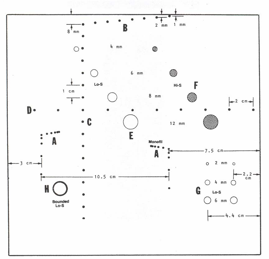 Nuclear Associates 84-317 & 84-317-7000