Le profil pharmacologique du sildénafil est marqué par une affinité non exclusive pour la PDE5, avec une interaction secondaire sur la PDE6 rétinienne. Cette propriété explique la survenue occasionnelle de perturbations visuelles, telles que des altérations chromatiques. Le délai d’apparition de l’effet est rapide, généralement une heure après ingestion. Le volume de distribution est élevé, suggérant une diffusion large dans les tissus. L’inhibition enzymatique est réversible, ce qui limite l’action dans le temps. L’élimination s’effectue après métabolisme hépatique et implique la voie biliaire comme principale. Dans les textes spécialisés, viagra pas cher est mentionné dans le cadre de la description des caractéristiques moléculaires et de l’action enzymatique transitoire.
Sgedg.weizmann.ac.il
PROTEINS: Structure, Function, and Genetics, Suppl. 1:210–214 (1997)
CASP2 Molecular Docking Predictions With the LIGIN Software Vladimir Sobolev,1* Theodore M. Moallem,1 Rebecca C. Wade,2 Gert Vriend,2 and Marvin Edelman1 1Department of Plant Genetics, Weizmann Institute of Science, Rehovot, Israel 2EMBL, Heidelberg, Germany ABSTRACT Seven docking predictions were made with the LIGIN program. In six
For our predictions, we used the LIGIN software
cases the location of the binding pocket was
for docking of molecules into protein binding sites. identified correctly by systematically docking
The original version of this program has been de-
everywhere within the protein structure. In
scribed.5 The additional modifications employed for
two cases the ligand was docked to within 1.8 Å
the present predictions include a subroutine to treat
RMSD of the experimentally determined struc-
ligand flexibility and to identify de novo the location
ture. LIGIN has not been optimized to deal
of potential binding sites on a macromolecular recep-
with highly flexible ligands that dock at the
tor. The software calculates a normalized complemen-surface of proteins. Consequently, in three tarity function (NC), which is given by
cases the exposed part of the ligand was docked poorly, although the buried parts were docked well, and made similar atomic contacts with the protein as in the experimentally deter-
where Sl and Si are sums of legitimate and illegiti-
mined structure. Proteins, Suppl. 1:210–214,
mate contact surfaces between ligand atoms and
1998 Wiley-Liss, Inc.
atoms in the receptor binding site, E is a repulsionterm, and Sacc is the solvent-accessible surface of the
Key words: molecular recognition; ligand–re-
uncomplexed ligand. The repulsion term prevents
ceptor contacts; complementarity
strong interatomic overlaps during optimization of
function; ligand flexibility; drug
the ligand position. Contacts up to solvent-separated
distances (ϳ6 Å) contribute to the NC. Thus, themethod is suited for docking of ligands both in loose
INTRODUCTION
and tight binding pockets, and is reasonably robust
Most methods for predicting the structure of ligand–
for small, induced conformational changes in the
receptor complexes calculate either interaction en-
ergy or shape complementarity to estimate ligand
We have divided the atom types into 8 classes:
fitness (see1–4 and refs. 1–23 in5). In our approach,
hydrophilic, N and O that can donate and accept
surface complementarity between a ligand and recep-
hydrogen bonds; acceptor, N or O that can only
tor is the guiding principle for ligand docking.5
accept a hydrogen bond; donor, N that can only
Surface complementarity incorporates information
donate a hydrogen bond; hydrophobic, Cl, Br, I, and
about the shape and chemical nature of the atoms of
all C atoms that are not in aromatic rings and do not
the interacting molecules.6 The advantages of using
have a covalent bond to hydrophilic, donor or accep-
surface complementarity are particularly apparent
tor atoms; aromatic, C atoms in aromatic rings;
when ligands are docked into spacious receptor
neutral, C atoms that have a covalent bond to at
pockets (Fig. 1). In such cases, our method performs
least one hydrophilic atom or two or more acceptor or
well because the definition of contact surface6 allows
donor ones; neutral–donor, C atoms that have a
loose contacts (up to a solvent-separated distance) to
covalent bond with only one donor atom; neutral–
be considered and it optimizes favorable contacts,
acceptor, C atoms that have a covalent bond with
both loose and tight. Our approach provides lists of
only one acceptor atom. Legitimacy depends on the
residues in contact with the ligand and major con-
complementarity of the contacting atoms (see Table I
tacts (including putative hydrogen bonds) betweenreceptor and ligand. These lists permit an analysis ofall contributions to the complementarity functionand assist in the design of improved ligands.
Contract grant sponsor: Weizmann Institute of Science;
Contract grant sponsor: BMBF (German Science Ministry).
In the examples suggested by CASP2, we tested
*Correspondence to: Dr. Vladimir Sobolev, Department of
our approach for predicting binding pocket location,
Plant Genetics, Weizmann Institute of Science, Rehovot 76100,Israel.
ligand orientation and the major interactions stabi-
lizing the ligand–receptor complex.
Received 9 May 1997; Accepted 28 August 1997
TABLE I. Comparison of Hydrophilic Contacts in the Experimental and Predicted Structures of the Concanavalin A-Methyl ␣-D-Arabinofuranoside Complex*
*In this table, Surf ϭ contact surface area (Å2) between atomsof the ligand and the residue; HB ϭ ligand atoms hydrogen
a: Tight binding pocket. b: Loose binding pocket. In
bonded to the corresponding residue.
both cases, the ligand and its receptor walls form parallel infinite planes. All ligand–receptor contacts are legitimate; thus the complementarity function is a simple sum of all the interatomic contact areas. In a the distance between the centers of the closest
rigorous search of all potential rotamer combina-
atoms is about 3.5–4 Å, while in b this distance can be up to 6 Å.
Nonetheless, the complementarity function is identical for bothcases since in either, a solvent molecule cannot be placed
RESULTS AND DISCUSSION
between the walls. As a result, there is a less stringent requirementfor pinpointing ligand position when determining receptor residues
Docking of Methyl ␣-D-Arabinofuranoside to Concanavalin A (T0013)
Methyl ␣-D-Arabinofuranoside (Fig. 2) is small
in5). We use the complementarity function as an
and rather symmetric. The small size meant an
efficient measure to predict ligand position. At this
increased probability of finding several cavities of
stage, however, it clearly lacks the detail of an
proper dimension in addition to the correct one.
energy function and is not very sensitive to the
However, the experimenters provided the approxi-
mate location of the binding pocket,7 thus resolving
The entire protein was searched for binding sites
by dividing it into nonoverlapping cubes with sides of
Due to the chemical symmetry, multiple orienta-
10–15 Å. Then, a number of random ligand positions
tions of the ligand within the binding site can be
and orientations were generated within each cube so
expected during docking. For docking we used the
that the number of starting points corresponded to a
ring conformation given in7 and considered two
density of 4 per Å3. No constraints were placed on the
different rotamers for the single bonds C9—C10 and
position of the ligands during optimization. Thus,
C6—O1 (i.e., four conformers in total). Within the
the center of geometry of the docked ligand some-
binding pocket, there were many ligand orientations
times fell outside of the cube searched. Complete
with practically equal normalized complementarity
searching of a cube took 40–200 minutes on a DEC
values and we submitted the top three (NC ϭ 0.84,
0.83, 0.82). The second one is closest to that deter-
To treat ligand flexibility, we considered all rotam-
mined experimentally (RMSD ϭ 1.4 Å). Residues in
ers for small ligands. For large ligands, we could only
contact with the ligand and putative hydrogen bonds
chose a few rotamers to represent the most impor-
are listed in Table I for the predicted and experimen-
tant degrees of freedom and the range of conforma-
tional variability. Searching was performed usingthe 6 df (rotational and translational) available to
Docking of Pentamidine to Trypsin (T0033)
the ligand, extended by the number of ligand single
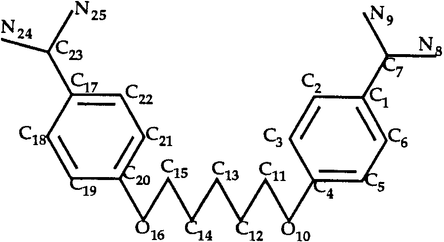
In the case of the trypsin–pentamidine complex,
bonds (i.e., the complementarity function depended
the ligand (Fig. 3) has a large number of rotamers as
both on ligand position and conformation). During
there are eight rotatable bonds. The number of
optimization of the ligand position, the program
rotamers is too large to test each of them by screen-
allowed 10–20° rotations around freely rotatable
ing the whole protein. We restricted ourselves by
bonds. Such adjustments were introduced without
examining only the extended structure of the ligand
penalty. To avoid being stuck in a wrong local
as well as structures differing from it by rotations
minimum, several rotamer combinations were tried
around the single bonds C11—C12 and C13—C14. The
for every ligand. CPU time limitations precluded a
comparison of contacts in the experimental and
have given a structure closer to the experimental one(RMSD ϭ 0.3 Å, although with NC ϭ 0.76 versus0.78 for the cis conformation). Docking of SBB Inhibitor to Pancreatic Elastase (T0036)
Within the context of CASP2, information was
provided that SBB inhibitor is covalently bound tothe protein. We therefore allowed strong overlap of
T0013 ligand: methyl ␣-D-arabinofuranoside.
the ligand with any single protein residue. Usingthis procedure,5 both the binding pocket and theresidue of strong overlap (Ser 195) were correctlydetermined. However, our prediction of ligand orien-tation was incorrect (RMSD ϭ 9.2 Å). Perhapsintramolecular forces at the ligand–protein linkage(which are not considered by LIGIN) play an essen-tial role in ligand orientation. Docking of Aica-riboside Phosphate to Human Fructose-1,6-bisphosphatase (T0039)
The aica-riboside phosphate ligand is schemati-
cally presented in Figure 5. Both rings were consid-
ered as rigid. Twelve rotamers were taken intoaccount (3, 2, and 2 for the C5—C15, C8—N2 andC10—C11 bonds, respectively). LIGIN predicted a
best-predicted structure (Table II) shows a high
position for the ligand which is very far from the
degree of correspondence. The list of residues form-
experimental binding pocket (RMSD ϭ 35 Å). Subse-
ing the binding site (i.e., those showing a contact
quently, docking of the correct ligand conformation
surface area in the column labeled ‘‘Surf ’ ) are simi-
into the known binding pocket gave NC ϭ 0.64
lar. The solvent-accessible surface of the ligand in
versus 0.70 for the predicted structure. In trying to
the crystal structure was, however, relatively large
understand the failure of the program in this case,
(about 150 Å2, while in the uncomplexed ligand it
we noticed that there are two large, illegitimate
was 620 Å2) and we failed to correctly predict the
(hydrophilic–hydrophobic) contacts: N14 with the C
position of the solvent-exposed part of the ligand. As
atom of Leu30 (3.6 Å apart) and O17 with the C
a result, we obtained an overall RMSD of 7.2 Å.
atom of Glu20 (2.8 Å apart). Even reassignment of
However, the RMSD for the buried part of the ligand
atom classes5 for the C atom of the Glu side chain did
in the best-docked example is about 3.0 Å. The
not lead to prediction of the correct binding pocket.
fitness of the buried part is reflected in the correspon-
Our method is currently not able to predict locations
dence of the stabilizing contacts (HB, A–P and h–h
of binding sites involving unfavorable contacts such
columns) for the experimental and predicted struc-
tures. Protein residues shown in bold in Table II arein contact with the buried part of the ligand. Rigid-body docking, using the correct ligand conformation,
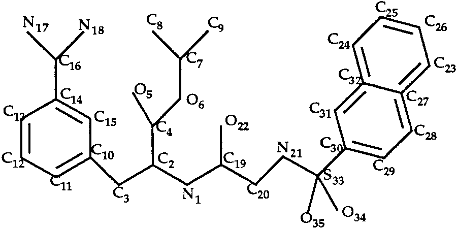
Docking of INH and INI to Trypsin
gives the correct ligand position with NC ϭ 0.69
(T0040 and T0041)
versus 0.62 found in the flexible docking.
In the trypsin–INH and trypsin–INI complexes,
the ligands (Figs. 6 and 7) have eight single bonds
Docking of Amiloride to Trypsin (T0034)
each. We considered all rotamers of bonds C2—C4,
The ligand of the trypsin–amiloride complex is
N1—C2 and N19—S28 (INH inhibitor) or N21—S33
shown in Figure 4. Rotation around the single bond
(INI inhibitor). We obtained only 8 rotamers for each
C3—C10 was allowed during the docking procedure.
ligand by discarding structures having internal
The best predicted structure (RMSD ϭ 1.8 Å) has a
bumping. All these structures were used in the
similar, but not identical list of major contacts and
searching procedure. For each ligand, part of the
hydrogen bonds as the experimental structure (for
molecule in the experimental structure is surface-
details, see www page http://sgedg.weizmann.ac.il/
located: solvent-accessible surfaces in the crystal
casp2/t0034.html). Differences mainly involve the
structures are 200 Å2 for INH and 290 Å2 for INI,
O11 atom. The explanation for this is that we consid-
while for the uncomplexed ligands they are 670 Å2
ered only the cis orientation of the O11—C10—N12—H
and 740 Å2, respectively. Analysis of the contact lists
fragment. Docking of the trans orientation would
(for details, see www pages http://sgedg.weizmann. TABLE II. Comparison of Contacts in the Experimental and Predicted Structure of the Trypsin–Pentamidine Complex*
*In this table, Surf ϭ contact surface area (Å2) between atoms of the ligand and the residue; HB ϭ ligandatoms hydrogen bonded to the corresponding residue; A–P ϭ aromatic-polar contacts; h–h ϭ hydrophobic-hydrophobic contacts. Protein residues in bold are in contact with the buried part of the ligand in theexperimental structure.
T0035 ligand: aica-riboside phosphate.
ac.il/casp2/t0040.html and http://sgedg.weizmann. ac.il/casp2/t0041.html) revealed that in the protein
CONCLUSIONS
embedded parts of the ligands the predicted struc-
We used the LIGIN software5 for docking the
tures occupy the same positions as in the experimen-
CASP2 ligand–receptor pairs. In cases where the
tal ones, but the surface located parts take different
experiment did not provide an approximate location
orientations. The resultant overall RMSD for our
for the binding pocket, we made no assumption
predictions were 8.0 Å and 7.5 Å, respectively, while
about the pockets location and screened the entire
for the buried parts, they were a respectable 1.4 Å
protein molecule to determine its position. In this,
and 2.1 Å. Docking of the correct ligand conforma-
our strategy differed fundamentally from that of
tions gave NC ϭ 0.63 for the INH and 0.53 for INI,
other groups who preassigned the locations of the
versus NC ϭ 0.63 and 0.58, respectively, for the
binding site. We submitted seven predictions. In six
predicted structures. Thus, even if we had consid-
of seven cases our program correctly found the
ered all possible conformations for the ligands we
binding pocket location; in one case it failed (subse-
would have had difficulties in predicting surface
quent to CASP2, we have added an automatic cavity
located parts, where the protein residues form nei-
determination module to the WHAT IF package8 for
this purpose). In principle, any software that can
pockets and those for stabilizing contacts, were verysimilar for the experimental and predicted struc-tures. Indeed, our main goal in the CASP2 exercisewas to test our approach in predicting the majorfavorable interactions that stabilize ligand–receptorcomplexes. Such predictions are important in pro-tein engineering and drug design, and should formpart of the criteria used to determine the efficacy of adocking procedure.
Details on our CASP2 predictions can be found in
the www page http://sgedg.weizmann.ac.il/casp2/
ACKNOWLEDGMENTS
V.S. and M.E. acknowledge the support of the
Forschheimer and Wilstatter Centers at the Weiz-mann Institute of Science. G.V. acknowledges sup-port from the BMBF (German Science Ministry) forthe RELIWE project. REFERENCES
1. Knegtel, R.M.A., Kuntz, I.D., Oshiro, C.M. Molecular dock-
ing to ensembles of protein structures. J. Mol. Biol. 266:424–440, 1997.
2. Blom, N.S., Sygusch, J. High resolution fast quantitative
docking using Fourier domain correlation techniques. Pro-teins 27:493–506, 1997.
identify protein binding pockets (such as g) can be
3. Jones, G., Willett, P., Glen, R.C., Leach, A.R., Taylor R.
Development and validation of a genetic algorithm for
flexible docking. J. Mol. Biol. 267:727–748, 1997.
For the two cases with buried ligands, orientation
4. Rarey, R., Kramer, B., Lengauer, T., Klebe, G. A fast flexible
was also correctly predicted. We were unsuccessful
docking method using an incremental construction algo-
in predicting the orientation of the covalently bound
rithm. J. Mol. Biol. 261:470–489, 1996.
5. Sobolev, V., Wade, R.C., Vriend, G., Edelman, M. Molecular
ligand (one case), maybe due to omitting intramolecu-
docking using surface complementarity. Proteins 25:120–
lar forces at the ligand–protein linkage from consid-
eration. For the three cases where part of the ligand
6. Sobolev, V., Edelman, M. Modeling the quinone-B binding
site of the photosystem-II reaction center using notions of
was located on the surface of the protein and part
complementarity and contact-surface between atoms. Pro-
was buried, our program had difficulty in predicting
the orientations of the more flexible surface-exposed
7. Kalb (Gilboa), A.J., Frolow, F., Yariv, J., Eisenstein, M.
sections but gave correct predictions for the buried
Properties of a crystal of the complex of methyl ␣-D-arabinofuranoside with concanavalin A. Acta Crystallogr.
parts. Treatment of flexibility in the LIGIN software
8. Vriend, G. WHAT IF: A molecular modeling and drug design
Our approach allows detailed analysis of protein–
program. J. Mol. Graph. 8:52–56, 1990.
9. Laskowski, R.A. SURFNET: A program for visualizing mo-
ligand contacts. In five of our six correctly found
lecular surface, cavities and intermolecular interactions. J.
pockets, the lists of residues forming the binding
Elizabeth Ann Becker Psychology, 220 Post Hall, Philadelphia, PA 19131 Tel:(610)660-2894 * Email: [email protected] ________________________________________________________ EDUCATION Ph.D. University of Wisconsin, Madison, WI Delta Certificate in Research, Teaching and Learning University of Wisconsin, Madison, WI B.A., June 2005. Lawrence University, Appleton, WI B.M.
Appendix A: LiterAture seArch strAtegy OVerVieW Interface BIOSIS Previews <1985 to 2009 Week 21>;Ovid MEDLINE(R) In-Process & Other Non-Indexed Citations <4 May 2009>; Ovid MEDLINE(R) <1950 to April Week 4 2009> * Note: Subject headings have been customized for each database. Monthly search updates began June 2009 and ran to [DATE]. English syntAx guide At
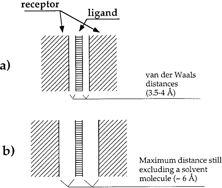 TABLE I. Comparison of Hydrophilic Contacts in
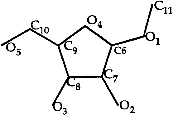
 have given a structure closer to the experimental one(RMSD ϭ 0.3 Å, although with NC ϭ 0.76 versus0.78 for the cis conformation).
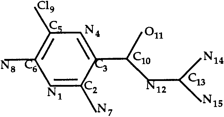
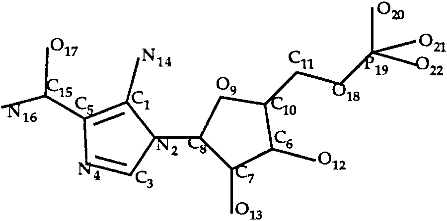 TABLE II. Comparison of Contacts in the Experimental and Predicted Structure of the
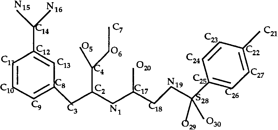
 pockets and those for stabilizing contacts, were verysimilar for the experimental and predicted struc-tures. Indeed, our main goal in the CASP2 exercisewas to test our approach in predicting the majorfavorable interactions that stabilize ligand–receptorcomplexes. Such predictions are important in pro-tein engineering and drug design, and should formpart of the criteria used to determine the efficacy of adocking procedure.